Catégorie : Technical

  • VCA vs DCA in pro mixing consoles: complete technical guide

    VCA and DCA grouping are two of the most important — and most confused — concepts in professional mixing. Even experienced engineers occasionally use the terms interchangeably, which obscures meaningful technical differences. Understanding what VCAs and DCAs actually do, how they differ, and when each is the right choice is essential for working pro audio engineers, particularly those moving between analog and digital console workflows or between recording and live sound applications. This guide cuts through the terminology confusion to provide a clear technical foundation.

    The fundamentals: what each term means

    VCA stands for Voltage-Controlled Amplifier. A VCA is an analog circuit that varies signal gain in response to a control voltage. The audio signal passes through the analog VCA chip (typically an SSL VCA, dbx VCA, or similar) on its way to the channel output, and the gain varies based on the control voltage applied. VCAs are physical components in analog and hybrid consoles.

    DCA stands for Digitally-Controlled Amplifier in some usages, or Digital Control Assignment in others. A DCA in a digital console controls the digital level of an audio signal in DSP — there’s no physical amplifier component, just a software gain stage that responds to the fader position assigned to the DCA group.

    The fundamental functional difference: VCAs control physical amplifier circuits in the analog signal path; DCAs control digital gain stages in DSP. In operational terms, both are used the same way — assign multiple channels to a group fader, move the group fader, and all assigned channels move proportionally. The technical implementations are fundamentally different.

    For broader signal flow context, see mixing console signal flow pro explained.

    Why the distinction matters

    Several practical implications follow from the technical difference:

    1. Signal path integrity. Moving a VCA group fader changes the analog control voltage to the assigned VCA chips, varying analog signal gain. The audio signal stays in the analog domain throughout. Moving a DCA group fader changes the digital gain in DSP — entirely within the digital domain. There’s no analog-to-digital conversion involved with DCAs because the signal is already digital.

    2. Audible difference. In well-designed VCA chips (modern SSL VCA, dbx 2150, THAT Corp 2180), there’s no audible coloration from the VCA itself at typical operating levels. In digital DCA implementations, there’s no audible difference at all because it’s just digital gain math. In practice, both VCA and DCA grouping are sonically transparent; engineers shouldn’t expect either to add character.

    3. Behavior at extreme settings. VCAs have measurable distortion characteristics at high signal levels approaching their linear operating limits. Modern flagship VCAs (THAT 2180A) handle extreme dynamics gracefully but can produce detectable harmonics at very hot input signals. DCAs in DSP are bit-perfect at any gain setting — the only constraint is internal precision (typically 32-bit or 64-bit floating-point in flagship digital consoles).

    4. Failure modes. VCAs can fail in analog consoles after long service — a common vintage console maintenance issue. DCAs can’t fail in any analogous way because they’re software constructs. This affects long-term ownership economics. See pro mixing console maintenance and care guide.

    Where you find each in 2026

    VCA grouping appears on:

    DCA grouping appears on:

    In hybrid consoles, the terminology gets fuzzy. Some manufacturers describe their digital control of analog VCAs as « VCA grouping » (because the actual amplification is VCA-based) while others describe it as « DCA grouping » (because the control is digital). The technical reality is that both descriptions are partially correct.

    How VCA and DCA grouping is used in pro applications

    The functional applications are essentially identical regardless of underlying technology:

    Drum kit grouping. Assigning kick, snare, toms, overheads, room mics to a drum VCA/DCA. The engineer can ride the entire drum bus with one fader.

    Vocal stack grouping. Lead vocal, harmonies, doubles, ad-libs assigned to a vocal VCA/DCA. The engineer rides the entire vocal section with one fader.

    Orchestral section grouping. Strings, brass, woodwinds, percussion each assigned to their own VCA/DCA. The conductor’s section levels can be ridden as units.

    Live sound band grouping. All instruments to « band » VCA/DCA, all vocals to « vocals » VCA/DCA, allowing fast band-vs-vocals balance adjustments during a show.

    Theater/musical grouping. Each scene’s active mics assigned to scene-specific VCA/DCAs, allowing fast scene transitions via single fader moves.

    Broadcast grouping. Each program element (talent, music, ambient, effects) on its own VCA/DCA for fast production mixing.

    For specific live sound applications, see arena/festival live sound setup walkthrough.

    VCA/DCA spill, mute, and additional functions

    Beyond simple level grouping, modern consoles offer additional VCA/DCA functions:

    Spill (or « open » or « expand ») — pressing the VCA/DCA’s spill button sends the assigned channels to the layer-1 fader bank for individual fader access without leaving the group view. Most flagship digital consoles support multiple-level spill.

    Mute group integration. VCA/DCA groups can be combined with mute groups for complex muting behavior — for example, muting all drums for an a capella verse without disturbing fader settings.

    Solo group integration. Soloing the VCA/DCA solos all assigned channels at once, useful for isolating a section while still hearing internal balance.

    Surround panning groups. On flagship surround consoles, VCA/DCA grouping can include linked surround pan position, allowing entire sections to be panned as a unit.

    Snapshot recall. VCA/DCA assignments are typically part of the snapshot recall system — a single snapshot can change all group assignments instantly for scene-based productions.

    Common technical confusions

    Several technical confusions appear repeatedly:

    1. « VCAs sound better than DCAs. » This is wrong. Modern VCAs and DCAs are both essentially transparent at typical operating levels. Engineers who believe they hear a difference are usually responding to something else (analog signal path coloration, console-specific sonic character, operational ergonomics).

    2. « DCAs add latency. » This is wrong. DCAs are essentially gain math in DSP — no additional latency beyond what’s already in the console’s digital signal path. The console’s overall latency is determined by its DSP architecture, not by whether you use DCA grouping.

    3. « VCA grouping changes the analog character of the channels. » This is wrong. VCAs control the level of an already-existing analog signal; they don’t change the harmonic content or character of that signal. Whatever character your channel strips deliver is independent of whether they’re VCA-grouped.

    4. « VCAs pre-fader/post-fader behavior is the same as DCAs. » This is mostly correct but with subtleties. Both VCA and DCA grouping is post-fader and post-pan in standard configurations. Some consoles offer pre-fader VCA grouping options for specific applications.

    5. « DCA grouping lets you ride sends without affecting the fader. » This is correct in some implementations and not others — depends on the specific console’s implementation. Worth checking on your specific console.

    VCA vs subgroup buses: a different distinction

    A separate confusion involves VCA/DCA versus actual subgroup buses:

    VCA/DCA grouping controls multiple channels with one fader without summing them to a separate bus. The signal still goes to its original destination (typically the master bus); the VCA/DCA just controls level proportionally.

    Subgroup buses sum multiple channels to a separate stereo (or mono) bus, which is then routed to the master. Subgrouping changes the signal path; VCA/DCA grouping doesn’t.

    This matters because:

    • Subgroup buses allow group-level processing (compression, EQ) on the summed group signal
    • VCA/DCA grouping doesn’t allow group-level processing — it’s just level control
    • For drum bus compression, subgroup is required, not just VCA/DCA grouping
    • For simple level riding, VCA/DCA is more efficient than subgrouping

    Many flagship consoles offer both subgrouping AND VCA/DCA grouping, with the engineer choosing which approach best fits each application.

    Bottom line

    VCA and DCA grouping are functionally similar tools for controlling multiple channels with one fader, but they’re technically different — VCAs are analog amplifier circuits, DCAs are digital gain stages. In modern flagship consoles, both are essentially transparent and operationally equivalent. Engineers should understand the distinction for technical accuracy and for context when comparing analog and digital console architectures, but in daily operation, the right answer is usually whatever group control your console provides — VCA or DCA.

    For the broader context on professional mixing consoles, return to our professional mixing console 2026 expert guide.

  • Mixing console signal flow: complete pro audio technical guide

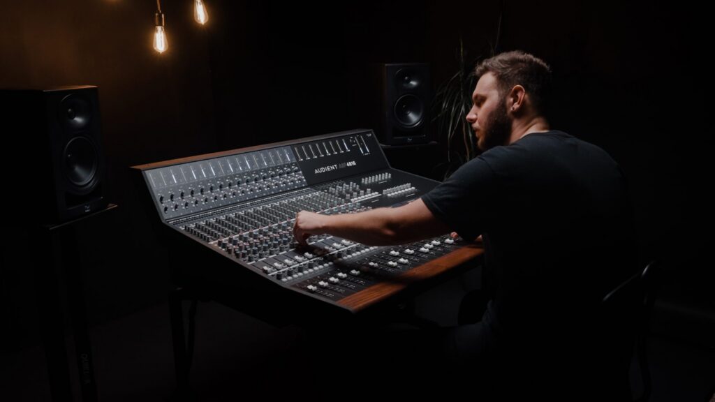
    Understanding professional mixing console signal flow is foundational for working pro audio engineers. While the basics — input through channel strip to master bus through outputs — are familiar to anyone who’s used a mixer, professional consoles introduce architectural complexity that requires careful study: in-line versus split topologies, pre- and post-fader send routing, insert point placement, multiple bus structures, monitor matrix design, and the difference between channel summing topology and bus summing topology. This guide provides a comprehensive technical foundation for engineers working at the flagship and high-end commercial tier.

    The fundamental signal path

    A professional mixing console’s signal path follows this general structure:

    1. Input stage — mic preamp or line input, with input gain control and high-pass filter
    2. Channel strip processing — typically EQ, dynamics, with order configurable on flagship consoles
    3. Insert point — analog or digital insert send/return for outboard processing
    4. Channel fader and pan — primary level and stereo placement control
    5. Bus routing — assigns the channel signal to subgroup buses, master bus, and matrix
    6. Aux sends — sends derived from the channel signal for monitor mixes, effects sends, and broadcast feeds
    7. Master section processing — bus compressor, master EQ, monitor matrix
    8. Output stage — analog output to stage I/O, broadcast feed, or recording rig

    The order of stages 2-5 varies by console and configuration. Some consoles allow swapping the order of dynamics and EQ; others fix the order. Insert points may appear pre- or post-EQ depending on console design.

    In-line vs split topology

    The most fundamental architectural distinction in professional consoles is in-line versus split topology:

    In-line topology combines two signal paths per physical channel strip — the input path (signal from a microphone or line source going to the recording medium) and the monitor return path (signal coming back from the recorder for monitoring). Each fader can control either path or both. This topology was introduced on the SSL 4000B in 1979 and became standard for tracking consoles thereafter.

    In-line consoles include all modern SSL frames (Origin, Duality), Neve Genesys, API 1608-II, Midas Heritage 3000, and most modern flagship analog consoles.

    Split topology uses separate input strips and monitor return strips. The engineer mixes monitor returns on one section of the console while another section handles input routing. This topology was standard for early-1970s flagships and remains in use on some specialty consoles, particularly mastering consoles and some API Legacy configurations.

    Split topology requires more channel strips for equivalent capability but offers cleaner operational separation between input and monitor functions.

    Pre-fader vs post-fader sends

    Aux sends (used for monitor mixes, headphone feeds, effects sends, broadcast subfeeds) can be derived from the channel signal at different points:

    Pre-fader sends take the signal before the channel fader. Moving the channel fader doesn’t affect the pre-fader send level. This is essential for:

    • Monitor mixes in a recording session — the talent’s headphone mix shouldn’t change when the engineer rides the channel fader for the recorded mix
    • Live sound monitor mixes — performers’ in-ear or wedge mixes shouldn’t change when the FOH engineer makes mix adjustments
    • Broadcast subfeeds — international feed levels shouldn’t change with the host program mix

    Post-fader sends take the signal after the channel fader. Moving the channel fader proportionally affects the post-fader send level. This is essential for:

    • Effects sends — when you mute a vocal channel, you want the reverb send to mute proportionally so reverb tail doesn’t continue without the dry signal
    • Recording feeds — when you mute a channel for the program, the recording feed should mute too
    • Subgroup feeds to bus processors

    Most flagship consoles offer per-send configuration of pre- or post-fader behavior. Some consoles offer pre-EQ versus post-EQ pre-fader options for additional flexibility.

    For specific application context, see VCA vs DCA explained.

    Insert points: location matters

    Channel inserts allow outboard processors to be inserted into the channel signal path. The location of the insert point affects what processing it can do:

    Pre-EQ insert — outboard signal is processed before the channel EQ. Used for outboard mic preamps (when the console preamp is being bypassed), for transient designers and gates that should operate on raw signal, and for de-essers.

    Post-EQ pre-dynamics insert — outboard signal is processed after EQ but before the channel compressor. Used for parallel compression configurations and for outboard processors that should benefit from EQ shaping but precede dynamic control.

    Post-dynamics insert — outboard signal is processed after both EQ and channel dynamics. Used for outboard processors that should operate on the fully-shaped channel signal (saturation, distortion, additional limiting).

    Pre-fader insert — outboard signal is processed before the channel fader. Used for processors that should respond to channel processing but be affected by fader rides.

    Post-fader insert — outboard signal is processed after the channel fader. Rare; used for specific applications where the processor should respond to fader-level signal.

    Most flagship consoles offer configurable insert point placement. Some consoles are more flexible than others; budget that flexibility into your console choice.

    Subgroup buses, master bus, and matrix

    Beyond individual channel routing, professional consoles offer several bus structures:

    Subgroup buses are intermediate stereo (or mono) buses that sum multiple channels for group-level processing. Drum bus, vocal bus, instrument bus are common configurations. Subgroup buses can be processed (with bus compressors, EQs, additional outboard) before being routed to the master bus.

    Master bus is the main stereo (or surround) output bus that drives the primary recording feed, FOH output, or broadcast main feed. The master bus typically has dedicated processing — bus compressor on SSL frames, master EQ on Neve frames, comprehensive metering, and monitoring controls.

    Matrix outputs are configurable buses that can take any combination of channels, subgroups, and master bus to create custom output mixes. Common applications include:

    • Theater speaker zone feeds (separate level for front-of-house, balcony, side-fills)
    • Broadcast subfeeds (host country feed, international feed, world feed all from same source)
    • Recording stems (separate drum stem, vocal stem, instrument stem for post-production)
    • Live recording feeds (separate feed to recording rig with different processing than FOH)

    For multi-format broadcast applications, see multi-format routing for broadcast mixing consoles.

    Channel summing vs bus summing topology

    The way analog consoles sum signals matters sonically:

    Channel summing topology describes how individual channels combine before reaching the bus stage. Most analog consoles use voltage-mode summing through resistor networks driving an op-amp summing stage. The character of this stage affects the console’s overall sound — particularly how the console behaves at high channel counts with many simultaneous signals.

    Bus summing topology describes how the master bus combines its inputs. Neve consoles traditionally use transformer summing on the bus output (contributing harmonic content). SSL consoles use IC op-amp summing (cleaner, less harmonic content). API consoles use discrete op-amp summing with output transformers (different from both Neve and SSL).

    These topology differences are part of why different analog consoles sound different — they’re not just about channel strip processing, they’re about how the console behaves when summing many simultaneous channels.

    For broader sonic context, see SSL vs Neve comparison and digital vs analog pro mixing console comparison.

    Monitor matrix and control room signal flow

    The monitor matrix is the section that handles control room and headphone monitoring. Professional monitor matrices include:

    • Source selection — switch between master bus, recording return, alternate sources, headphones-only sources
    • Speaker selection — multiple speaker pairs (mains, near-fields, alternate references), with calibrated level matching
    • Headphone matrix — multiple headphone outputs with independent source selection (engineer monitor different from talent monitor)
    • Talkback — engineer voice routing to talent headphones, with auto-dim of program signal
    • Sum/cut/dim — fast monitor controls for level adjustment without changing main mix
    • Mono fold-down — checking mono compatibility of stereo mixes

    Mastering consoles take this further with extensive reference monitoring switching — see SPL DMC mastering console guide and best mixing console for mastering studio 2026.

    Digital console signal flow specifics

    Digital consoles (DiGiCo Quantum, Avid VENUE S6L, Yamaha Rivage) implement the same logical signal flow but in DSP rather than analog circuits. Specific differences:

    • Bit depth and precision matter. Flagship digital consoles use 32-bit or 64-bit floating-point internal precision to maintain headroom across complex signal paths.
    • Latency accumulates through processing stages. Each plugin or DSP stage adds latency; flagship consoles use lookahead and delay compensation to maintain phase coherence.
    • Routing flexibility is greater. Digital consoles can typically route any input to any bus with arbitrary signal flow — analog consoles are constrained by physical patch points.
    • Insert point options are more numerous. Digital consoles often offer 6+ insert points per channel versus 1-2 on analog consoles.
    • Format flexibility is built in. Digital consoles handle stereo, surround, immersive within the same processing engine; analog consoles require explicit signal path provisioning for each format.

    Bottom line

    Professional mixing console signal flow is foundational engineering knowledge. Understanding in-line versus split topology, pre- and post-fader send routing, insert point placement, subgroup and matrix bus structure, and console-specific summing topology helps engineers make informed equipment choices and operate consoles efficiently in pro contexts. For working pro audio professionals, this knowledge is essential — particularly for engineers moving between analog and digital workflows or between recording and broadcast applications.

    For the broader context on professional mixing consoles, return to our professional mixing console 2026 expert guide.

  • Pro mixing console maintenance and care: complete owner’s guide

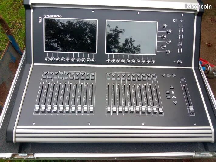
    A flagship mixing console is a 15-25 year capital investment. Whether you’re operating a vintage SSL 4000G+, a modern Neve Genesys G32, a DiGiCo Quantum 7, or a Studer Vista 9, the console requires ongoing maintenance to deliver flagship performance over its operational life. This guide covers the maintenance and care requirements of professional mixing consoles from a working pro audio operations perspective — what needs doing, when it needs doing, what it costs, and who should do the work.

    This guide assumes a flagship or high-end commercial tier console. Project-tier mixers and consumer-grade equipment have fundamentally different maintenance economics that aren’t addressed here.

    Daily and weekly maintenance

    The most basic ongoing maintenance is preventive operation:

    Daily:

    • Visual inspection of console surface for spilled liquids, debris, or impact damage
    • Verification that all faders move smoothly through full travel
    • Confirmation that no error indicators are showing on master section displays
    • Verification of master section monitoring matrix function (control room, headphones, talkback)

    Weekly:

    • Compressed air cleaning of fader tracks and rotary control surfaces
    • Visual inspection of patchbays for bent pins or damaged jacks
    • Verification of network connectivity and redundant path failover (digital consoles)
    • Check of automation system memory utilization

    Monthly:

    • Surface cleaning with appropriate console-grade cleaning products (avoid alcohol or solvents that can damage component surfaces)
    • Patchbay reseating to maintain contact integrity
    • Backup of session/show files and console configuration (especially digital consoles)
    • Verification of all I/O connections and signal flow integrity

    Quarterly:

    • Power supply voltage measurement and verification (analog consoles especially)
    • Fan and ventilation cleaning (digital console DSP engines, analog console PSU racks)
    • Full backup of console operating system, automation data, and stored sessions/snapshots

    Annual service procedures

    Once per year, more thorough service procedures are recommended:

    Analog console annual service:

    • Full surface deep cleaning (modules can be removed for thorough cleaning)
    • Fader track cleaning and conductive plastic strip inspection
    • Switch contact cleaning with appropriate contact cleaner (DeoxIT or equivalent)
    • Power supply capacitor inspection for bulging or leakage
    • Full automation system check (Encore, Total Recall, GML Flying Faders depending on console)
    • Recalibration of channel strip gain matching
    • EQ frequency response verification on sample channels
    • Bus summing integrity check
    • Master section bus compressor function verification

    Digital console annual service:

    • DSP engine fan cleaning and ventilation verification
    • Power supply UPS battery replacement (typically every 3-4 years, but inspected annually)
    • Network switch firmware updates and configuration backup
    • Software update to current stable release (after testing on backup unit if available)
    • Snapshot system database integrity check
    • Touch screen calibration and functional test
    • Full I/O signal flow verification
    • Latency measurement across all processing paths

    Annual service for a flagship analog console typically requires 2-4 days of skilled technician time and costs 3,000-8,000 USD depending on console size and complexity. Annual service for a flagship digital console typically requires 1-2 days and costs 2,000-5,000 USD.

    Major service: capacitor replacement (recap)

    The largest maintenance event in an analog console’s operational life is electrolytic capacitor replacement, typically required every 15-25 years:

    Why recap matters. Electrolytic capacitors degrade through electrochemical processes that cause dielectric breakdown over time. As capacitors age, their effective capacitance decreases and their equivalent series resistance (ESR) increases. The audible result is loss of low-frequency extension, reduction in headroom, and increased noise floor. The performance degradation is gradual and often unnoticed until comparison with a recently-recapped reference.

    What gets replaced. A typical 1980s-1990s flagship console has 5,000-10,000 capacitors across channel strips, master section, and power supplies. Recap involves systematic replacement of every electrolytic capacitor, with new components matched to original specifications.

    Who does the work. Specialist firms (Funky Junk in the UK, Vintage King Audio in the US, dedicated SSL/Neve service technicians) handle full recaps. The work cannot be done by general electronics technicians without console-specific expertise — wrong capacitor types or values can damage the console.

    Cost. Full recap of a 32-48 channel flagship console typically runs 30,000-60,000 USD. Larger 60-72 channel frames can run 60,000-100,000 USD.

    Downtime. Full recap typically takes 8-16 weeks depending on console size and specialist availability. Studios planning major service should schedule around major production cycles.

    For comprehensive vintage restoration context, see vintage mixing console restoration guide.

    Fader maintenance and replacement

    Console faders are the most heavily-used component on the surface and require ongoing attention:

    Routine cleaning. Every 6-12 months, faders should be exercised through full travel to identify intermittent contact issues, sluggish movement, or audible scratchiness. Compressed air can clear immediate dust accumulation; deeper issues require disassembly.

    Reconditioning. Every 3-7 years, faders should be reconditioned — disassembled, cleaned of accumulated oil and debris on the conductive plastic strip, and recalibrated. Cost: typically 200-400 USD per fader for full reconditioning. A 32-channel console might require 8,000-15,000 USD for full fader reconditioning.

    Replacement. Faders can fail outright, with the conductive plastic strip showing wear that can’t be cleaned. Replacement faders are available for most flagship consoles but may have lead times. Cost varies by console; flagship-grade faders can run 200-600 USD per replacement.

    Motorized fader maintenance (digital and hybrid consoles). Motorized faders have additional motor assemblies, position sensors, and control electronics that require periodic service. Most motorized fader designs in flagship consoles are robust but eventually need motor replacement after 10-15 years of heavy use.

    Switch and rotary control maintenance

    Switches and rotary potentiometers accumulate oxidation, dust, and (in heavily-used consoles) accumulated fingerprint residue:

    Routine cleaning. DeoxIT D5 or equivalent contact cleaner, applied sparingly to switch contacts and rotary potentiometer wiper contacts. Excessive cleaner causes more problems than it solves — proper application uses a small amount and works the control through full travel multiple times.

    Replacement of failed components. Failed switches and pots are common in vintage consoles. Replacement requires console-specific component availability — original switches are often no longer in production, and substitution requires careful matching of resistance values, switching topology, and mechanical fit.

    Encoder maintenance (digital consoles). Rotary encoders on digital consoles typically don’t fail mechanically but can have bouncing contact issues that cause jumpy parameter response. Most flagship digital consoles use optical encoders that are robust but eventually need cleaning or replacement.

    Power supply care

    Power supplies are often the weakest link in long-term reliability:

    Voltage measurement and adjustment. Annual measurement of all PSU rails (typically ±15V, ±18V, +5V, and console-specific rails) verifies that PSU performance is within specifications. Adjustment may be required as components age.

    Capacitor replacement in PSU. PSU capacitors typically need replacement on a similar schedule to console capacitors (15-25 years). Some studios proactively rebuild PSUs alongside annual service to avoid catastrophic failure during sessions.

    UPS and conditioning. Flagship consoles should always operate on conditioned power with UPS protection. Furman, Equi=Tech, or comparable power conditioning protects PSU components from voltage transients. UPS protection provides graceful shutdown in the event of power loss — particularly critical for digital consoles where power loss can corrupt session files.

    Cooling. PSU racks accumulate dust and require periodic cleaning. Inadequate cooling shortens PSU component life dramatically.

    Common troubleshooting issues

    Several recurring issues appear in pro console operations:

    Intermittent channel issues. Most often caused by oxidized contacts in patchbays, switches, or backplane connectors. Systematic exercise of all relevant connections often resolves intermittent issues without component replacement.

    Channel level mismatch. Drift in channel gain calibration over time. Annual calibration as part of preventive maintenance addresses this.

    Bus summing imbalance. Drift in bus mixing components over time. Requires technician-level attention to identify and correct.

    Automation system glitches. Most often firmware-related on modern consoles. Update to current firmware version after testing.

    Motorized fader hunting or jitter. Position sensor or motor assembly issues. Often resolved by recalibration; sometimes requires hardware replacement.

    Network connectivity issues (digital consoles). Most often cable, switch, or fiber transceiver issues. Systematic isolation testing identifies the failed component.

    Specialist service providers

    Several types of specialists serve the pro console maintenance market:

    Manufacturer factory service. SSL Factory Services, AMS Neve, DiGiCo, Avid, Yamaha all offer factory-level service for current-production consoles and many legacy products. Factory service is typically the most expensive option but provides authoritative repair quality.

    Authorized service centers. Most flagship manufacturers maintain authorized service centers in major regional markets. Service quality is generally comparable to factory service at modest cost savings.

    Independent specialists. Funky Junk (UK), Vintage King Audio’s restoration team (US), Brent Averill Engineering for Neve specifically, and various regional independent technicians provide specialized service. Quality varies by reputation; established specialists deliver factory-equivalent work.

    In-house technical staff. Studios with sufficient operational scale (multiple flagship rooms, 15+ year operational horizon) often justify in-house technical staff. A senior console technician runs 80,000-130,000 USD annually fully-loaded but provides immediate response to issues and consistent maintenance quality.

    Long-term ownership economics

    Realistic annual maintenance budgets for flagship consoles:

    • Modern flagship analog (10-15 years old): 5,000-12,000 USD/year
    • Active vintage flagship (15-30 years old): 10,000-25,000 USD/year
    • Highly-used vintage flagship (30+ years old, daily commercial use): 20,000-40,000 USD/year
    • Modern flagship digital (5-10 years old): 3,000-8,000 USD/year
    • Older digital flagship (10-15 years old): 5,000-15,000 USD/year (rising as components age)

    These figures don’t include major service events (recap, fader replacement, automation updates) which represent 10-25% of console value spread across 15-25 year operational horizons.

    Bottom line

    Professional mixing console maintenance is an ongoing operational responsibility, not an occasional event. Studios committing to flagship console ownership should budget for routine maintenance, plan for major service events, and identify specialist service relationships before problems arise. For long-term operations, the maintenance commitment is part of what justifies flagship console economics — a well-maintained console delivers world-class sound for 15-25 years; a neglected console becomes operationally compromised within 5 years of purchase.

    For the broader context on professional mixing consoles, return to our professional mixing console 2026 expert guide.

  • Multi-format routing in broadcast mixing consoles: pro guide

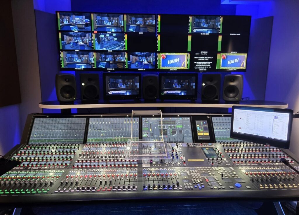
    Modern broadcast mixing operations require simultaneous multi-format routing — stereo, 5.1, 7.1, immersive (Dolby Atmos, MPEG-H), multilingual feeds, and various legacy or specialized output formats. A single sports broadcast might generate an English-language stereo feed, an English-language 5.1 feed, an international 5.1 feed, a separate Spanish-language stereo feed, an Atmos feed for streaming partners, and isolated music feeds for partners — all from a single console operation. This routing complexity requires console architecture specifically designed for the demands of multi-format broadcast. This guide covers the technical foundations of multi-format routing for broadcast engineers and facility planners.

    For broader broadcast console context, see best mixing console for broadcast TV/radio 2026 and broadcast TV/radio mixing console setup guide.

    The fundamental routing challenge

    Multi-format broadcast routing differs from recording or live sound routing in several fundamental ways:

    1. Simultaneous formats. A broadcast operation must deliver multiple format outputs simultaneously — stereo + 5.1 + Atmos + dialogue-only feed all from the same source content, all at the same time, all with appropriate level normalization and metering.

    2. Format-specific signal flow. Each output format has its own signal flow requirements. Stereo needs L+R; 5.1 needs L+R+C+LFE+Ls+Rs; 7.1.4 immersive needs L+R+C+LFE+Ls+Rs+Lrs+Rrs+Lts+Rts+Lts+Rts (top channels). Each format requires appropriate panning, summing, and routing within the console.

    3. Loudness compliance per format. Each output format has loudness compliance requirements (ATSC A/85 for US TV, EBU R128 for European broadcast, plus format-specific normalization). The console (or downstream processor) must deliver compliant output for each format.

    4. Multilingual feed isolation. International broadcast often delivers separate language feeds — English commentary, Spanish commentary, host nation commentary — each as separate program output. Mic isolation between commentary positions and the main mix must be operationally clean.

    5. Failover and redundancy. All format outputs must remain available through hardware failures, with automatic failover to redundant signal paths.

    Format-specific considerations

    Stereo

    Stereo remains the dominant broadcast format for radio and many TV applications. Modern broadcast stereo work involves:

    • Stereo bus summing with phase coherence verification
    • Stereo metering (peak meters, VU meters, loudness meters)
    • Mono fold-down checking for stereo broadcasts that may be received in mono
    • Stereo panning for single sources (commentary, music, ambient effects)

    All flagship broadcast consoles (Studer Vista, Lawo mc², Calrec, SSL System T) handle stereo as a baseline format with extensive per-channel pan, balance, and routing controls.

    5.1 surround

    5.1 surround (L+R+C+LFE+Ls+Rs) remains the most common immersive format for broadcast TV and film. Console requirements include:

    • 5.1 panner per channel — typically a 2D surround panner with center percentage control and LFE level send
    • 5.1 bus summing with proper LFE filtering (typically 80 Hz crossover, sometimes 120 Hz for music applications)
    • 5.1 metering — six-channel peak metering with proper Dolby/SMPTE specifications
    • 5.1 monitoring — control room and headphone monitoring of 5.1 with appropriate downmix matrix for stereo monitoring as needed

    Most flagship broadcast consoles handle 5.1 natively. The differences between manufacturers are in panner ergonomics, monitor matrix flexibility, and metering quality.

    7.1 surround

    7.1 (adding rear surround channels Lrs+Rrs to 5.1) is used for some film post-production applications and increasingly for broadcast. Most flagship broadcast consoles support 7.1 with appropriate panner and bus configurations.

    Dolby Atmos and immersive (7.1.4 / 9.1.6)

    Dolby Atmos and similar immersive formats use object-based audio with bed channels (typically 7.1.4 — the standard 7.1 plus four height/top channels) plus discrete audio objects with metadata. Broadcast Atmos delivery typically involves:

    • Bed channel mixing in 7.1.4 with appropriate height channel panning
    • Object-based audio with metadata (position in 3D space, dialogue/music/effects classification)
    • Render to delivery format (typically 7.1.4 PCM bed + object metadata, packaged in TrueHD/Dolby Digital Plus codecs for delivery)
    • Monitoring in proper Atmos monitoring environment (7.1.4 speakers minimum, ideally 9.1.6 reference)

    Atmos support varies significantly across console manufacturers. Some flagship broadcast consoles handle Atmos natively in the surface and DSP; others require external Atmos processing (Dolby Renderer, Avid MTRX hardware processing). Lawo mc² has extensive Atmos integration; Calrec Apollo and Argo support Atmos via integration paths; Studer Vista X handles Atmos via partnership configurations.

    MPEG-H 3D Audio

    MPEG-H 3D Audio is a competing immersive standard, primarily used in some Asian markets and emerging streaming applications. MPEG-H delivery is similar to Atmos in object-based architecture but uses different metadata and encoding. Console support for MPEG-H is less universal than Atmos in 2026.

    Multilingual and program subfeed routing

    A typical international sports broadcast operation generates multiple program feeds:

    Main program (host country language): Full mix with commentary, music, ambient effects, and any additional production elements.

    International feed (no commentary): Music, ambient effects, and crowd/match audio without commentary track. International broadcasters add their own language commentary.

    World feed (broadcast partners): Modified version of international feed with technical specifications matching IBC or other industry standards.

    Per-language commentary feeds: Separate audio paths from each commentary position, available as isolated outputs for international broadcaster routing.

    Talent/dialogue isolation: Full mic-only feeds for post-production access.

    The console must route to all these outputs simultaneously, with appropriate level normalization, format conversion (e.g., stereo for some feeds, 5.1 for others), and metering.

    Network audio and IP routing

    Modern broadcast multi-format routing increasingly happens over IP networks rather than legacy MADI/SDI infrastructure:

    SMPTE ST 2110-30 (audio over IP): Standard for transporting audio over IP in broadcast facilities. ST 2110-30 transports PCM audio with low latency and tight clock synchronization.

    ST 2110-20/22 (video over IP): Transports uncompressed (ST 2110-20) or compressed (ST 2110-22) video alongside audio. For audio engineers, the relevant aspect is that the audio routing infrastructure typically shares network with video routing.

    NMOS IS-04 and IS-05: Discovery and routing protocols for ST 2110 networks. NMOS allows the console to discover available audio sources and routes on the network without manual configuration.

    AES67: Lower-level audio-over-IP standard, typically used as building block for ST 2110-30 or as standalone audio network. Compatible with Dante (with appropriate configuration) and many other IP audio implementations.

    Dante: Audinate’s proprietary audio-over-IP standard, widely deployed but less prevalent in broadcast IP infrastructure than AES67/ST 2110.

    Lawo mc² is the most mature IP-native broadcast console as of 2026; Calrec Argo and SSL System T are other strong IP-native choices for new broadcast infrastructure builds.

    Patch and routing management

    Multi-format broadcast operations require sophisticated patch and routing management:

    Console source/destination matrix: Logical source labeling (camera mics, commentary positions, music sources, ambient mics) mapped to console channels with consistent identification across operators.

    Snapshot recall of routing configurations: Each program (different sports event, news segment, music show) may use different routing. Snapshots store these configurations for instant recall.

    Operator workflow tools: VisTool (Studer), Sapphire (Lawo), Hydra2 router control (Calrec) provide screen-based routing management alongside console operation.

    Disaster recovery routing: Pre-configured emergency routes that activate on hardware failure. A modern broadcast operation should be operationally functional even with a console failure, switching to backup audio paths via the routing matrix.

    For technical foundation context, see mixing console signal flow pro explained.

    Loudness management across formats

    Each output format has different loudness compliance requirements:

    Stereo broadcast: ATSC A/85 (-24 LKFS in US), EBU R128 (-23 LUFS in EU) 5.1 broadcast: Same loudness target as stereo, but with proper surround measurement Atmos broadcast: Dialogue normalization at -27 dB dialnorm (US) or matching loudness target Streaming targets: Various; typically -16 to -14 LUFS for music streaming, -23 to -16 LUFS for film/TV

    Console architecture must support format-appropriate loudness measurement and processing. Most flagship broadcast consoles include integrated loudness meters per output bus; some delegate loudness management to downstream processors (Junger, Linear Acoustic, Dolby DP-590).

    Bottom line

    Multi-format routing is a defining technical challenge of modern broadcast operations. Flagship broadcast consoles (Studer Vista X, Lawo mc² 96, Calrec Apollo Plus / Argo, SSL System T S500) handle simultaneous stereo, 5.1, 7.1, Atmos, and multilingual feed routing as core capability — but the implementation details vary significantly between manufacturers. For new broadcast facility builds and console specifications, multi-format routing capability should be evaluated specifically against operational requirements rather than relying on manufacturer marketing claims.

    For the broader context on professional mixing consoles, return to our professional mixing console 2026 expert guide.